Choice-of-the-capacitors--Pi_Hat_Pals.docx
Constraints:
-
Height <= 7mm
-
Total capacitance needs to reach 4.29 mF, i.e. 4290 uF
-
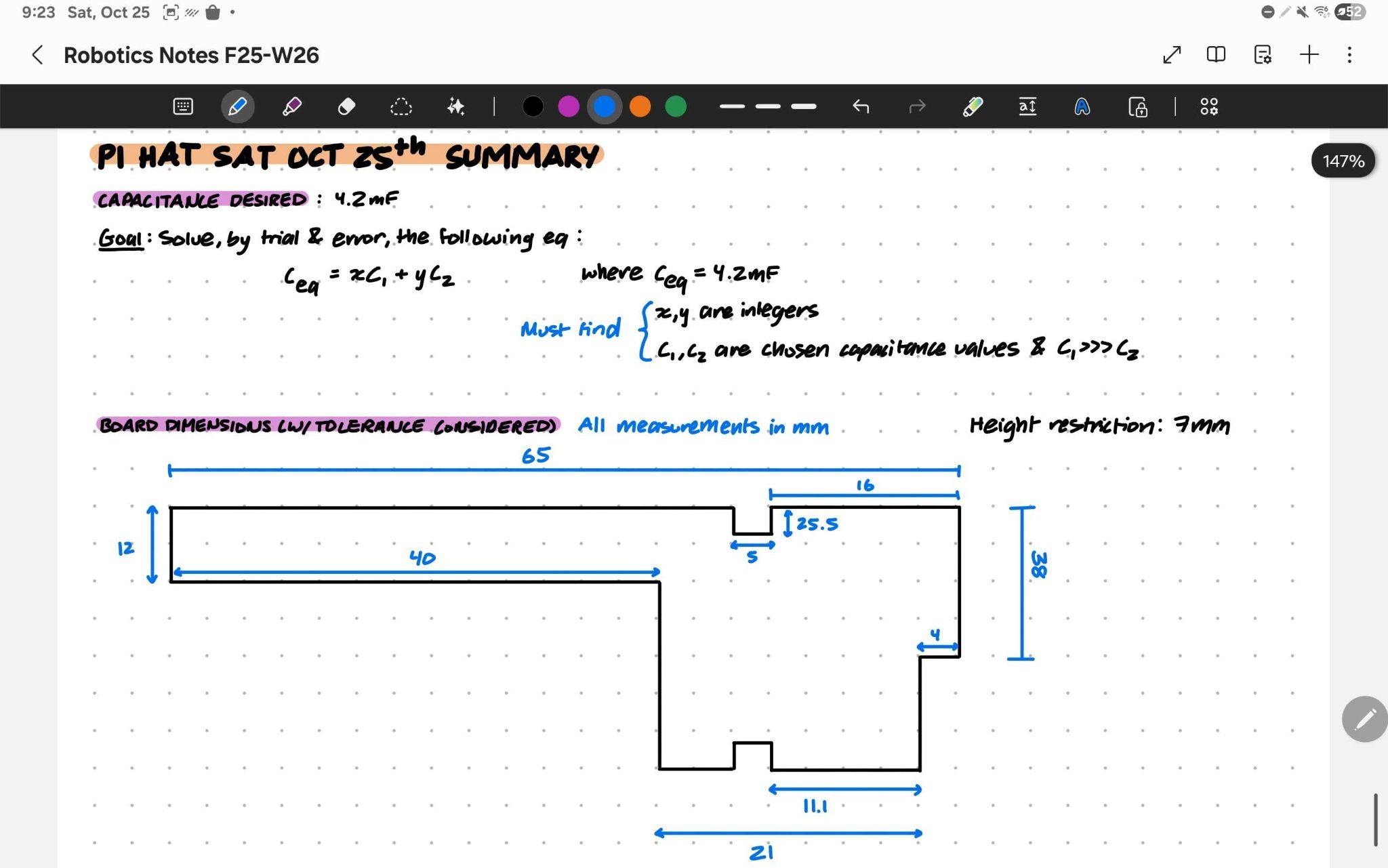
Area need should not exceed the total available area of 1792 mm^2
(calculated by 12 * 65 + 21 * (56-12) + 4 * (38-12) - 2 * 2 * 4 = 1792 mm^2)
 {width="5.767716535433071in"
height="3.611111111111111in"}
*Combinations:* We chose the Ceramic Capacitors to be the ones with smaller capacitance, and Aluminum Electrolytic Capacitors to be the ones with greater capacitance.
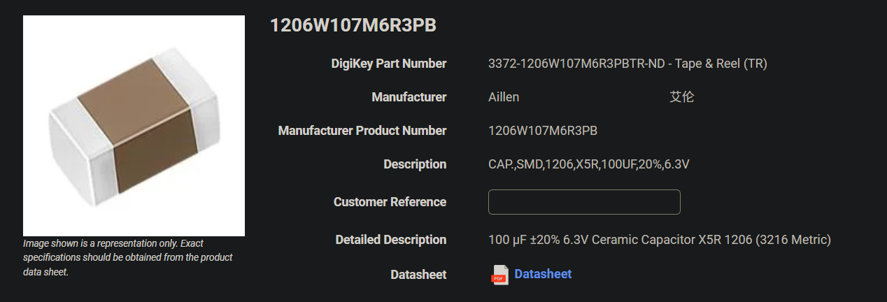
[For the]{.underline} [Ceramic Capacitors, we found the one shown
below]{.underline}:
 {width="5.768055555555556in"
height="1.9652777777777777in"} Link: [1206W107M6R3PB Aillen |
Capacitors | DigiKey
Marketplace]{.underline}
It has 100 uF each, and each of them will occupy an area of 3.2 * 1.6 = 5.12 mm^2.
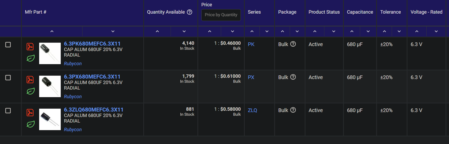
[For the]{.underline} [Aluminum Electrolytic Capacitors, we found the following]{.underline}:
 {width="5.768055555555556in"
height="1.8576388888888888in"}
Link: [680 µF Aluminum Electrolytic Capacitors | Electronic Components Distributor DigiKey]{.underline}
Their diameter is 6.3 mm, and their height is 12.5 mm. Each of them has a capacitance of 680 uF.
All of them share a same area needed, computed by its diameter times height, since we would bend them by 90°.
The best combination we found is: 5 of those candidate Aluminum Electrolytic Capacitors plus 9 of those candidate Ceramic Capacitors, resulting in a capacitance of 4300 uF, which is close to the ideal capacitance (4290 uF) we want. In this case, the area needed will be 3.2 * 1.6 * 9 + 12.5 * 6.3 * 5 = 439.83 mm^2 < 1792 mm^2.
There will be enough room to establish a space between each capacitor. All capacitors will be placed in parallel with each other.
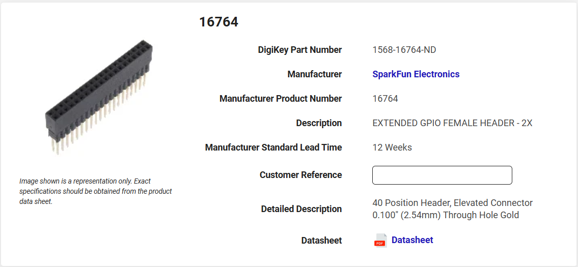
[One option for the female connectors is the 40 Position Header, Elevated Connector 0.100" (2.54mm) Through Hole Gold:]{.underline}
 {width="5.767716535433071in"
height="2.6666666666666665in"}
What remains to be completed:
Find a diode (no diode needed apparently) find a female connector (>9mm connector)
Start brainstorming on the schematics of our PCB
Put picture of layout on layout
make sure the pin corresponds to the actual pinout using datasheet
todo:
- add 10uF capacitor 0603, sacrifice chunkier
- change 470 to 680